Friday, 9 December 2016

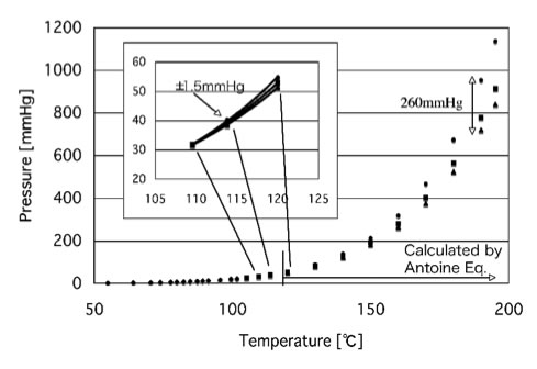
How Boiling point varies with Vapor Pressure - Antonie Equation


Hey visitors......!!!
The most basic thing that many engineers were aware of that is Boiling point varies with Vapour pressure, and i'll bet you that many of those Engineers donno the exact reason for this, and today i'll reveal that under hidden reason for that behavior of solvents.

For that you should be aware of some damn basic things like what does exactly Vapour pressure, Boiling point means.

What is Vapour Pressure ?

Vapour Pressure means the pressure exerted by the vapour on the surface of liquid at equilibrium, Usually vapour wont have any Vapour pressures, the vapour pressure is the property of solvents, every solvent will have their respective vapour pressures.

What is Boiling Point ?

Boiling point is nothing but a point of saturation where the vapour pressure of a solvent equals the atmospheric pressure, simply toluene is a solvent, whose boiling point is 110.6°C, and at that boiling point the vapour pressure of toluene will be 760 torr, [Dont get confused Torr means mmHg only]. And same is the case with every solvents boiling point.

Also Read:


How to Select a Condenser?
What Does a TR exactly means? 
How to Calculate the Energy of Steam?


Right now, you got a clear idea of the Vapour Pressure & Boiling point, So now i'll start my show about describing the relation ship between Vapour Pressure and Boiling point, the only relation that describes the relation between these two parameters is Antonie Equation.

By using Antonie equation we can calculate the boiling point of solvent at different pressures, it also means that the boiling point of solvents will decrease with Vacuum, and we can calculate it theoretically. In fact, this is the first calculation that i've learned after joining the Pharma Industry.

 The basic Antonie Equation is,

Log P = A - B / ( T + C ),

A, B, C are Antonie Constants,

P is Vapour Pressure, T is Boiling point.

Just remember one thing, while selecting the Antonie constants, there are many set of constants available, and they will vary with the units of Pressure that you  choose.

So, by now, if you are new to this calculation, this known equation will look something special to you,

Recommended Posts For You:


Many of the Pharma Operations will include "Distill off solvent under vacuum below temperature X°C" ,  here while they include word vacuum just because we can distill off the solvent below its regular boiling point.

I'll show you a small demo and Anyway i'll tell you how to use this practically,

"Distill off toluene under vacuum below 60°C with vacuum NLT 650 mmHg at the end of distillation",

This means the product that is present in our reaction mass is stable upto 60°C, and after that the product may degrade,

And here vacuum should be NLT 650 mmHg at the end of distillation, so now just try to calculate the boiling point at 650 mmHg,

For that you need to know the Antonie constants of Toluene,


Antonie constants data here

A =  6.95, B = 1344.8, C = 219.482,

the Vacuum should be NLT 650 mmHg, so the pressure should be P = 760 - 650 = 110 mmHg.

Log (110 ) = 6.95 - 1344.8 / ( T + 219.482 )

Solving for T, T = 54.4°C.

So, this means at 650 mmHg the boiling point of Toluene will be 54.4°C, which means it came down from 110.6°C to 54.4°C.


So, if you understand what i delivered above, just say cheers, 

Still any doubts feel free to contact me,

Comments were most appreciated...............!!!


Also Read:


 About The Author

Hi! I am Ajay Kumar Kalva, Currently serving as the CEO of this site, a tech geek by passion, and a chemical process engineer by profession, i'm interested in writing articles regarding technology, hacking and pharma technology.
Follow Me on Twitter AjaySpectator & Computer Innovations


Wednesday, 30 November 2016

LMTD Correction Factor


Back after a long gap, and i got many queries asking about LMTD, and how to decide the LMTD factor, so today i gonna explain you exactly what does LMTD mean and how does it vary and what factors does have influence over LMTD.

What is LMTD ?


LMTD means Logarthemic Mean Temperature Difference, there are many ways to calculate Mean value, i.e., Average value of the temperatures of fluid streams like Arthematic mean, Geometric mean, Harmonic mean etc, but those all were limited for a certain extent, while coming to the case where two fluid streams were involved, it is difficult to calculate the mean of those, for such cases there is a need to develop one expression which can define the exact mean value, so there our LMTD was born,


The Basic expression which defines LMTD is,


LMTD =  ( ( T1 - T2 ) - ( T3 - T4 ) ) / Log [ ( T1 - T2 ) / ( T3 - T4 ) ],


So, with an example i'll explain you the way of calculating the LMTD value,


Calculation :


Let us we are having two process fluid where heat transfer taking place, hot fluid inlet is having 80 deg C and out let if having 70 deg C, and the cold fluid is having inlet temperature of 25 deg C and outlet temperature of 45 deg C, so for this we need to calculate the LMTD,


Giving notations for the temperatures, Th1 = 90 deg C, Th2 = 75 deg C,

Tc1 = 25 deg C, Tc2 = 35 deg C,


LMTD = ( ( Th1 - Tc2 ) - ( Th2 - Tc1 ) ) / Log [ ( Th1 - Tc2 ) / ( Th2 - Tc1 ) ]

            =   ( ( 90 - 35 ) - ( 75 - 25 ) ) / Log [ ( 90 - 35 ) / ( 75 - 25 ) ]
            
           =    (  55 - 50 ) / Log [ 55 / 50 ] 

          =     5 / 0.04  = 125

So our LMTD value is 125 deg C, for Counter current flow,

Now calculating for Parallel flow,


LMTD = ( ( Th1 - Tc1 ) - ( Th2 - Tc2 ) ) / Log [ ( Th1 - Tc1 ) / ( Th2 - Tc2 ) ]

             =  ( ( 90 - 25 ) - ( 75 - 35 ) ) / Log [ ( 90 - 25 ) / ( 75 - 35 ) ]

             =  ( 65 - 40 ) / Log [ 65 / 40 ]  =  119 

So our LMTD value in Parallel flow is 119 deg C.

So by now you gotta clear picture of calculating the LMTD. and also one thing you can observe is the LMTD value is somewhat higher in Counter flow than parallel flow, so the Heat transfer profile is better in counter flow.


Factors influencing LMTD : 

The expression of Heat transfer rate is given in the expression, 

Q = U x A x LMTD,

The value of Q will increase if LMTD increases, 

LMTD = Q / [ U x A ],

So from the above form it is clear that if Heat Transfer Area increases then the LMTD will decrease, and same is the case of Overall Heat Transfer Co-efficient also.

Coming to LMTD correction factor, you need to know some thing, when actually there is need for LMTD correction factor.

When does it require ?

Usually our condensers in process industry will be Shell & Tube heat exchangers, where the concept of passes will arise, usually there will be two passes for cold fluid and single pass for hot fluid, simply a 1,2-shell & tube heat exchanger, for effective heat transfer rate the hot fluid will be passed through shell and cold fluid on tube side, as our main motto is to remove heat from hot fluid to cold fluid and let our hot fluid condense, so there wont be any problem if our hot fluid exchanges heat with the shell to atmosphere, but we need to use the utility energy very effectively,

So, while coming across these cases, our cold fluid will be passing through one counter flow and one parallel flow with respect to hot fluid and we can calculate either parallel flow LMTD or Counter flow LMTD, but together cannot, due tot these kind of circumstances the concept of LMTD correction factor arises,,

LMTD Correction Factor :

Overall LMTD = LMTD of Counter flow  x  Correction factor ( F ),

Usually many of the engineers will considers the Value of F as 0.9, but actually there is a way to calculate the value of F theoretically, i'll demonstrate it below,

R = ( Ta - Tb ) / ( tb - ta )

P = ( tb - ta ) / ( Ta - ta )

Ta , Tb  - Shell in & out temperatures,

ta , tb    -  Tube in & out temperatures.

If R =!  1, 

α  = [ ( 1 - ( RxP ) ) / ( 1 - P ) ] ^ ( 1 / N ),       S =  ( α - 1 ) / ( α - R ),


F = Q x Ln [ ( 1 - S ) / ( 1 -RS ) ] / [ ( R - 1 ) Ln [ ( 2 - S( R+1 - Q ) ) / ( 2 - S(R+1 + Q ) ) ] 

Where, Q = [ ( R^2 +1 )^0.5 ],

if R = 1,

S = P / (N - ( N- 1 ) P ),

F = 1.414 S /[ ( 1 - S ) Ln [ ( 2 - 0.59S ) / ( 2 - 3.41S ) ]

That's it..........!!! You're done,

If you understood the above calculation part, then Say cheers,

If any doubt got arised then simply ping me, i'll be there to resolve your queries........!!!

Comments are most appreciated.........!!!

About The Author


Hi! I am Ajay Kumar Kalva, Currently serving as the CEO of this site, a tech geek by passion, and a chemical process engineer by profession, i'm interested in writing articles regarding technology, hacking and pharma technology.
Follow Me on Twitter AjaySpectator & Computer Innovations

Friday, 28 October 2016

Vent Sizing for Pressure Vessels / Equipments


Hello Everyone...........!!

Today here i gonna explain you about vent sizing of pressure vessels and process equipments based on the way of usage. Simply take the case of a Batch reactor, what will happen if there is no vent or pressure relief valve during a reaction........??

The result may vary with the size of the reactor, Simply the presence of a Relief valve will relief the over pressure that was developed inside and protects the reactor, Usually the reactor will be having a pressure resistance which is known as Design pressure, if the reactor is felt with more than the design pressure, then there may be a chance for explosion, and i said there may be a chance of explosion because after manufacturing of reactor there will be some recommended tests that were to be done like pressure test, spark test[if its a GLR], etc. While performing a pressure test, the vendor will cross the limit of design pressure and gives a specification called Test Pressure, which means the pressure upto which the test was carried out.  

So, now i'll tell you when there is a need for Vent/Relief valve:

Vapour / Gas removal rate < = Vapour / Gas generation rate,

If the above condition is satisfied, then there requires a Relief valve / Vent for the system.

The major factors that will decide the Vent size were:

  • Maximum Vapour/Gas Generation rate,
  • Type of fluid inside the container, whether its a gas or liquid.

In case of Maximum generation rate, If we need to vent out Vapour / Gas that was generated, then simply calculate the size from below equation:

V = A x S = 0.785 x D x D x S,

here, V = Volumetric flowrate in Cu.m / hr,

D is Diameter of Vent,

A is Cross sectional area of the vent neck,

S is the velocity with which the vapour / gas will escape, 

And coming to second case, if the Container / Vessel is containing any gas, then there wont be any problem because if its a solvent then there is a chance that solvent may be transform to vapours and create some vapour pressure, but as it is a Gas then whatever the pressure that is accumulated, that will be kept off like that. 

One more important term, named as WCM [ Worst Credible Maloperation ], Which means the highest pressure developed due to the maloperation responsible for the generation of vapour / Gas.
The calculation should obey the criteria, i.e., pressure that was developed during the WCM should safely pass through the vent provided, or the Relief valve should respond to the WCM pressure with a minimal response time 

The approach to Relief sizing depends on 2 cases:
  • Fire case,
  • Reaction case 

For a fire,

Vapour generation rate = Heat from fire / Latent heat of vaporization 

For a chemical reaction,

Vapour generation rate = Reaction rate x Reaction Enthalpy / Latent heat of vaporization.

So after getting the vapour generation rate, you can go with above mentioned equation, V = A x S,

if there is any problem while calculation, then better go with a direct equation which was developed & Proposed by Leung's Long form eqn.

A = [ m x q ] / G [ { (VxT/m)+(dP/dT)}^0.5  +  {Cp x dT}^0.5  ] ^2


m - Initial mass in vessel (Kg),
q - Heat evolution rate per unit mass in vessel(Watt/Kg),
G - Vent flow capacity per unit area at set pressure(Kg/Sq.m),
V - Vessel volume(Cu.m),
T - Vessel temperature(K),
dP/dT - Rate of change of vapour pressure with temperature,
Cp - Specific heat ( J/Kg.K),
dT - difference of temperature between Maximum allowable pressure & Set pressure ( °K),

As per the Equilibrium rate model, the Value of G [ vent flow capacity] can be calculated as below,

G = (dP/dT) x SQRT(T/Cp) = hfg / [ Vfg x SQRT( Cp x T) ]

That's it..........!!

Now, here i'll demonstrate the above mentioned formula with a calculation.

Consider a 10 KL reactor, having MOC SS316 with a design pressure of 3.2 Bar, and maximum allowable pressure as 4.2 Bar, i.e., 30% excess to design pressure


Average 
Pressure Bar
3.2 
4.16 

Bubble point temperature °C 
110 
120.5 
115.3 
Heat release rate ( watt/Kg) 
1150 
1660 
1405 
Liquid density ( Kg/Cu.m) 
847 
835 
841 
Vapor density (Kg/Cu.m) 
3.75 
4.62 
4.19 
Latent heat (KJ/Kg) 
674.9 
663.0 
668.95 
Liquid specific heat (KJ/Kg.K) 
1.96 
1.96 
1.96 
dP/dT 
8300 
9500 

Vfg (Cu.m/Kg) 
0.2655 
0.2153 
0.2404 

Using equation developed from Equilibrium rate model,

At 3.2 Bar pressure, G = 0.5 x (dP/dT) x SQRT(T/C) = 0.5 * 8300 * SQRT( 383/1960)

= 2385 Kg/Sq.m S.

At 4.16 Bar Pressure, G = 0.5 * 9500 * SQRT(393.15/1960) = 2128.73 Kg/Sq.m S

The average value of 2385 & 2128.73 for G gives  2256.5 Kg/Sq.m S.

Now, we need to calculate the venting area from  Leung's Long form eqn.

dP/dT = ( 4.16 - 3.2 ) x 10^5 / ( 120.5 - 110 ) = 9143 N/Sq.m K


A =  [ 1500 * 1405 ] / 2256.5 [ { 10 * 288.5 * 9143/1500 }^0.5 +{1960 * 10.5 }^0.5] ^2

    =  0.0122 Sq.m

D = SQRT(0.0122/0.785) = 0.125 m = 5" (inch)


I think, now you got an exact idea of solving the data for getting the venting area for Pressure vessel,

Any queries please feel free to ping me...........................!!

Comments are Most appreciated....!!


About The Author


Hi! I am Ajay Kumar Kalva, Currently serving as the CEO of this site, a tech geek by passion, and a chemical process engineer by profession, i'm interested in writing articles regarding technology, hacking and pharma technology.
Follow Me on Twitter AjaySpectator & Computer Innovations


Sunday, 16 October 2016

Vacuum Steam Technology


Hello guyzz.... first of all happy Weekend to all.......!!

Today i gonna explain you a emerging technology, which is simply a revolution in industries and which is very hard to believe by all, i.e., Vacuum Steam.

Now, i'll explain you its features briefly, it is simply  a low temperature steam produces at a high pressure and later the pressure will be reduced with an equipment like inlet control valve or a pressure reducing system which can reduce the produced pressure very rapidly like a vacuum pump. 

May be its very difficult to believe the above and i'll tell you that we can produce this with the help of steam from boiler, and even we can automate it with just two interlock systems.


Recommended Posts:


[How To]Calculate Energy of Steam
[How To] Design a Chiller Plant?


The higher the pressure, the higher the temperature of saturated steam. At regular atmospheric pressure, saturated steam is roughly 100°C. Saturated steam generated from boilers, however, is generally much higher in temperature because it is generated at higher pressures. This steam (positive pressure steam) is therefore frequently used in industry for heating processes requiring temperatures above 100°C.
Alternatively, producing saturated steam for heating processes below 100°C is also possible. Such steam is often referred to as vacuum steam because it requires pressures below regular atmospheric pressure. Vacuum steam is generally generated at higher pressures after which pressure is reduced by using equipment such as an inlet control valve. A vacuum pump is also usually used to help achieve lower pressures at start-up and enable the smooth release of condensate.
Use of vacuum steam requires careful temperature and pressure reading. To determine steam temperature, referring to a steam table such as the one above is recommended. For example, through this steam table, we can see that if a process requires saturated steam at temperatures of 60°C or 90°C, saturated steam pressures should be set to 19.946kPa and 70.182kPa, respectively.

Also Read:


Outlines for Preparation of Design Qualification Document 
Outlines for Preparation of Operational Qualification Document


How to Generate the Vacuum Steam.....??

All you need is a pressure reducing control system and a vacuum regulator with a HMI(Human Machine Interface), 

Purpose of Pressure Reducing control system:

When the steam enters the chamber containing water, then the water will gets heated up and then a secondary steam will start generating, then the pressure of the secondary steam will be similar to that of the external steam and we have to produce steam of temperature 83 deg C, 


so as per steam tables the pressure corresponding to 83 deg C temperature will be 410 mmHg abs, so the external steam should be turned off when ever the produced secondary steam pressure reaches 410 mmHg, so to control the inlet pressure of the external steam, a pressure reducing control system is used.

Purpose of Vacuum regulator:

Usually vacuum regulator works on the principle of Air to close Diaphragm system, whenever the generated secondary steam pressure exceeds 410 mmHg, immediately the vacuum regulator will starts it work and opens,


 then by the suction pressure of the vacuum the generated secondary pressure will be reduced to 410 mmHg, So to reduce the produced secondary steam pressure, a vacuum regulator is used.

Purposed of HMI(Human Machine Interface):


The use of HMI is very simple, it will co-ordinate with both the valves at a time and make them work alternatively with a set point, the set point will be set by the operator based on saturated steam tables data.

You can use the follow link to generate the Steam temperature by giving the steam pressure as input.   Click Here

Advantages of Vacuum Steam over Regular Steam and Hot Water:

1) Vacuum steam can be generated at required Low temperatures, which will hold the energy equivalent to the regular Steam and much higher than the energy of Hot water,

2) The time cycles of operations like distillation, drying, heating can be reduced without affecting the quality of the manufactured product,

3) The Efficiency of the Vacuum steam is much higher than that of the Regular steam and Hot water as Vacuum steam will support RAMP Heating, which is recommended for pharma operations.


That's it......!!! This is all about Vacuum Steam, hope everyone who read this should have understand,

 if you want to add up something about Vacuum steam just mail me,

Comments are most appreciated.....!!


Related Topics:


[How To] Calculate rate of Distillation in a Batch Reactor ? 
Outlines for Preparation of URS document
Do you know how pressure varies with altitude ??
[How To] Scale-up for an Agitation process ??


About The Author


Hi! I am Ajay Kumar Kalva, Currently serving as the CEO of this site, a tech geek by passion, and a chemical process engineer by profession, i'm interested in writing articles regarding technology, hacking and pharma technology.
Follow Me on Twitter AjaySpectator & Computer Innovations